Navigation
E-Services
'Talga' Institute
Email: m.burjanadze@agruni.edu.ge, Phone: 2 36 51 32; 599 14 54 13 Address: Georgia, Tbilisi, Sandro Euli 5, 0186
About Institute
234
Publication
98
Conference
20
Project/Grant
7
Intelligence Property
Institute "Wave" of Georgian Technical University carries out fundamental and applied scientific research activities. The scientific-research activities of the Institute are multilateral. In the first direction, we discuss the topic of the study of magnetic relaxation of highly anisotropic material in a paramagnetic state under conditions of zero and weak magnetic constant field. The second topic concerns the study of the physical, mechanical, chemical and biological properties of some alloys (materials alloyed with different substances) for their further use in the human body; The third topic is the studying and assessment of the radio-ecological condition of the urban environment, theoretical and experimental research. On these issues institute has prepared and submitted grant projects to the Shota Rustaveli National Science Foundation, involving young scientists from Georgia and a scientific consultant from Washington State University (US Transuranium and Uranium Registries, College of Pharmacy, Washington State University (Richland). In accordance with the rules established by the legislation of Georgia, Institute can carry out consulting and expert activities;
GTU Institute "Wave" can organize scientific conferences and other scientific events in accordance with the legislation of Georgia and the regulations of the University; Cooperate with Georgian and foreign scientific-research Institutions; Participate in international scientific events; As well as in the preparation and implementation of higher education programs; In the performance of undergraduate and graduate theses and dissertations by students; Involve students in scientific grant projects, local and international scientific conferences and research events; The Institute may carry out other activities provided by the legislation of Georgia and according the University regulations and the Statute of the Institute.
Structural Units
Scientific-Research Laboratory of "TALGA" Institute
Scientific Equipment
| Title of the equipment/device | Technical characteristics | Date of issue | Exploitation staring year | Usage/application | Purpose of usage/application | Technical condition |
| Oscillograph C1-49 | Measurement voltage range - 20 mV - 200 V; Measurement time interval range - 8 ms - 0.5 sec; Bandwidth 0 - 5.5 MHz; Signal amplitude measurement error - not more than 10%; Time interval measurement error - not more than 10%; Beam line width - 0.6 mm; Screen work area horizontally - 60 mm; Screen work area vertically - 36 mm; Supply voltage - 220 V 50 Hz, 115 V 400 Hz; Power consumption - 38 VA; Operating temperature range -30 + 50 degrees; Overall dimensions - 170 X 223 X 445 mm; Weight - 8.5 kg. """ | 1972 | 2010 | The device is used to observe and study the shape of electrical processes in the frequency range 0 - 5 MHz, for visual observation and to measure the values of amplitudes. | scientific | Operational - working condition |
| low-frequency generator ГНЧШ | The generator has two outputs with an output impedance of 5 ohms and 600 ohms. The output power of the generator with a matched load at a frequency of 1000 Hz is not less than 2 W. The output voltage at a frequency of 1000 Hz with a matched load at the output of 5 ohms changes to 3.4 V, and at the output of 600 - up to 36 V. Frequency error of generated oscillations - no more than ±(0.1% f + 2) Hz. Before connecting to the network, the generator must be grounded. It has a built-in digital frequency meter " | 1983 | 2009 | The purpose of the device is to generate sinusoidal electrical oscillations in the frequency range of 20 to 20,000 Hz. | scientific | Operational - working condition |
| Power supply ИЭПП | Laboratory power supply ИЭПП-2 allows to get at its outputs alternating voltages of 36 V at a load current of up to 1.5 A and 12 V at a current of up to 0.5 A, a stabilized DC voltage of 0.5 to 12 V at a current of up to 1 A, as well as an unstabilized direct voltage from 0 to 36 V at a current of up to 0.1 A. This device is powered by an AC power supply of 220 V. | 1986 | 2010 | The device can operate in both voltage stabilization mode and power stabilization mode, which is automatically set according to the source load. | scientific | Operational - working condition |
| Tester Ц4343 | In the case of AC voltage measurement, the input resistance of the device is 2 kohm /V, and in the case of DC voltage measurement - 20 kohm /V. The device is made of two versions of the device mounting plate. Tester Ц -4313 operates at an air temperature of -10 ... + 40 ° C at a relative humidity of up to 80%. The Ц -4313 tester uses a magnetoelectric type measuring mechanism with an internal magnet. The total deflection of current is 42.5 a. The frame has an impedance of 632 ± 3 ohms. | 1971 | 2008 | The device allows to measure voltage and current in AC and DC circuits, DC resistance, capacities, relative levels of alternating voltages. | scientific | Operational - working condition |
| Oscillograph C1-83 | Number of channels 2. Bandwidth (0 - 5) MHz. Growthing time 70 sec; Major error ± 4%. Maximum allowable of the maximum value of direct and alternating voltage: 160 V on the I and II imputs. At the input of the divider 1:10 200V Introduction Impedance: Direct introduction 1 MΩ / 35 picoF, Divider 1:10 10 MΩ / 15 picoF " | 1983 | 2010 | The C1-83 oscilloscope is designed for visual observation and study of electrical signals in the frequency range (0 - 5) MHz: capable of: measuring the amplitude and time parameters of the test signal; Receiving simultaneous images of two study signals; Present images of functional dependence between two signals in X-Y mode. C1-83 allows to measure voltages in the range 400 μV - 200 V and time intervals in the range of 400 nsec - 20 sec. | scientific | Operational - working condition |
| Camera-refrigerator | Type: two-chamber; Management type: electronic; Total useful volume: 290 l (± 10%); Useful volume of the refrigerator compartment: 216 l (± 10%); Freezer compartment capacity: 74 l Freezer compartment layout: bottom; Cooling system: ALL Around Cooling; Energy efficiency class: A +; Engine Type: Inverter Freon Type: R600A; Noise level: 38 dB; Maintaining temperature in case of power off: not less than 12 hours of fast freezing; Physical parameters; Size: 600X640X1700 mm (± 10%). | 2021 | 2022 | Used to store samples | scientific | Operational - working condition |
Scientific buildings
International Scientific Works
| Project number/ID | Project title | Name of the grant call | Funding organization | Grant budget (total) | Start/end dates | Principal investigator | Key personnel | Project Summary | Detailed description | Achieved results |
|---|---|---|---|---|---|---|---|---|---|---|
| MS-24-132 | High-temperature superconductors and their preparation | "Popularization of science and stimulation of scientific research in schools in mountainous regions of Georgia" | Shota Rustaveli Science Foundation of Georgia | 5000 | 29.09.2024-09.12.2024 | Magda Metskhvarishvili | Sophio Kobakhidze | One of the priority directions of research institutes and higher education institutions is to interest students in science from the very beginning of school. The development of natural sciences is a prerequisite for technological progress. Thus, the involvement of students in scientific work at an early age is a step forward for the country. This project is dedicated to one of the interesting and fascinating directions of physics - superconductivity. The goal of the project is for students to get acquainted with the phenomenon of superconductivity, the physical nature of high-temperature superconducting materials and to study their application in the modern world. To understand what difficulties are encountered in the use of this unique material and what goals are set by scientists interested in the research of these materials. Also, the goal of the project is for students to get acquainted with the technology of preparing ceramic substances and observe the Meissner effect. | Superconductors are materials that have zero resistance to the flow of current. This is one of the most important scientific discoveries of recent times. The theory that explains the behavior of superconductors is still under discussion. Superconductivity was first discovered by the Dutch physicist Heike Kamerlingh Onnes at the University of Leiden in 1911, when he cooled mercury to the temperature of liquid helium (4 K, 268C) [1]. Good conductors of electric current, such as gold and copper, do not enter the superconducting state at all, while relatively poor conductors such as Nb3Sn, Nb3Ga, and Nb3Ge are good superconductors at about 17.24 K. In 1986, A. Müller and J. Bednorz in Switzerland created a brittle ceramic compound [2] that became superconducting at 36 K. This discovery was significant because ceramics are conventional insulators. The behavior of the La-Ba-Cu-O compound of lanthanum, barium, copper, and oxygen, which Müller and Bednorz synthesized, was unclear. Müller and Bednorz's discovery caused great excitement in the field. Scientists around the world began to prepare ceramics in all possible combinations in search of a high transition temperature Tc. In 1987, lanthanum was replaced by yttrium in the Müller and Bednorz compound, and a remarkable transition temperature of 92 K was obtained. In the following period, replacing yttrium with rare earth elements allowed scientists to obtain compounds with transition temperatures of 115–125 K. The highest superconducting transition temperature among the compounds discovered today is about 160 K. The main characteristic feature of superconductivity, in addition to the transition of electrical resistance to zero, is also the expulsion of a permanent magnetic field from the sample. This effect was discovered by German physicists E. Meissner and R. Oxenfeld [3] and became known as the “Meissner-Oxenfeld effect”. The expulsion of a magnetic field was as amazing to physicists as the absence of resistance. A permanent magnetic field usually penetrates everything, and as a result, the magnetic field in the substance either increases slightly - such substances are called paramagnetic, or decreases slightly - diamagnetic. In superconductors, the magnetic field decreases to zero. They are ideal diamagnetic. It is important to find superconductors whose transition to the superconducting state occurs at room temperature. This will be a major advance in science and industry. Of particular importance is the creation of superconducting cables that will operate at room temperature, which will provide unprecedented power savings. References: 1. Dirk van Delft, Freezing physics, Heike Kamerling Onnes and the quest for cold, edited by Edita KNAW, Amsterdam, 2007. 2. J. G. Bednorz and K. A. Müller (1986). "Possible high Tcsuperconductivity in the Ba−La−Cu−O system". Z. Physik, B 64 (1): 189– 193. 3. Meissner W., Ochsenfeld R., Naturwiss, 1933,B.21, S.787 The project is in line with the goals and objectives of the competition, as the project is planned to be implemented in a school in a mountainous region of Georgia. As described in the expected results and project management implementation, the project includes a scientific and research part (description and conduct of an experiment (Meissner effect)), which will increase students' interest in natural sciences. | Final report 1. (1st month, Fig. 1) A meeting with students was held at the school and a lecture was held on the history of the discovery of high-temperature superconductors and the stages of further development. I had prepared a review material (D.1) and a presentation (D.2), which presented the history of the discovery of superconductivity, that it was discovered by Kamerlingh Onnes in 1911 in the Leiden laboratory. I explained the scheme of current transfer in ordinary conductors, and that this scheme does not apply to superconductors. Here, the current transfers Cooper pairs and there is a different theory. Kamerlingh Onnes studied low-temperature superconductors. In 1986, Bednorz and Muller discovered high-temperature superconductors. These were non-metals - ceramics. I also mentioned that they were in Georgia in 2007. Tbilisi State University hosted an international conference in physics on the topic: “High-temperature superconductivity: initial concept and new results”. The organizers, together with Tbilisi State University, were the Georgian National Science Foundation, the Max Planck Institute (Germany) and the University of Zurich (Switzerland). I introduced the students to the principle of operation of superconductors and their areas of application in the world. High-temperature superconducting cables have already been manufactured and are used in the world, they are used as strong magnets, and high-speed trains have been created. The students were instructed to prepare presentations for the next meeting on the topics; 1. What are superconductors and their areas of application; 2. What is the connection between superconductors and medicine. 3. Superconductors and CERN. 2. (2nd month, Fig. 2) A meeting was held with the students. The students had prepared presentations that they were given at the first meeting. In the first presentation (D.3), the students focused on superconducting magnets, which are used to accelerate particles in magnetic resonance imaging (MRI); on MTZ wires, which are used in everyday life. They provide higher power transmission, than metal cables and on “swallowing” trains, which were created in Japan (Tokyo-Nagoya) and China (Beijing and Shanghai). In the second presentation (D.4), the students presented the connection of superconducting materials with medicine. The main tool presented was magnetic resonance imaging (MRI), the most informative method of radiological research; magnetoencephalography), which measures magnetic fields generated by electrical currents in the brain. SQUID is the most sensitive device for measuring magnetic fields. It is used to measure the magnetic fields generated by blood circulation in the human body, allowing for non-invasive diagnosis of diseases. Magnetocardiography (MCG) also uses a SQUID device. The third presentation (D.5) showed how superconductors are used at CERN. To accelerate particles to high energies, a large current is required, so the magnets are surrounded by superconductors, for which they are cooled to 1.9 Kelvin, which is -271.3 degrees. This temperature is lower than the temperature of open space. CERN not only conducts fundamental research, but also cares about the well-being of humanity, for example, they created MRI, and they also laid the foundation for hadron therapy. Today, hadron therapy is the most promising method of treating oncological diseases. 3. (3rd month, Su.3) The project leader gave a presentation (D.6) on the preparation of high-temperature superconductors. It details which oxides are used to prepare Y〖Ba〗_2 〖Cu〗_3 O_7 - yttrium oxide Y_2 O_3; barium carbonate oxide BaCO_3; copper oxide CuO, their corresponding images and structures, their corresponding masses, the rod, with which they are mixed, the grinder, with which they are ground; the furnace, in which the firing takes place. I explained how the initial inspection of the sample is done. If it is received in a greenish form, the process must be started over. The green color indicates that there is insufficient oxygen in the sample. It is impossible to control the oxygen content according to the initial impurity. In order for the sample to receive the necessary oxygen, it must be burned at 500-600 C for 20 hours. The oxygen capture by the sample depends on the color. We can monitor the color every 5 hours using a microscope. The indicator of superconductivity is the Meissner effect, due to which a magnet attracts a superconductor. The project leader brought two superconducting samples to the students. The Meissner effect was demonstrated. Presentations depicting the Meissner effect were shown, which aroused great interest among the students. https://www.youtube.com/watch?v=VyOtIsnG71U https://www.youtube.com/watch?v=sU3av6FqwHs The students were divided into three groups and presented what was interesting and memorable to them. What did they learn from this project. At the end, the students were given notebooks, pastes, files, and printed informational materials about the discovery of superconductors as souvenirs. |
| FR-24-2178 | Protecting Public Health through Comprehensive Radon Monitoring and Dosimetry in Urban Tbilisi | Fundamental Research State Grant | Shota Rustaveli Science Foundation of Georgia | 240000 | 08.03.2025-08.03.2028 | George Tabatadze | Magda Metskhvarishvili - Coordinator Kakha Gorgadze Maia Avtandilashvili | The project aims to determine radon concentrations in the air of the urban environment of Tbilisi (apartments, schools, other industrial and public buildings and their surrounding areas). To assess the risks posed by radon to the health of the population of various administrative districts. To compile electronic maps of radon risk, which will be available to the population of Georgia, foreign organizations and other interested parties. | The issue is particularly relevant for Georgia, as the country’s geological formations are characterized by high uranium content; in addition, many buildings are constructed with locally produced materials. Therefore, radon is a potentially serious problem in Georgian conditions. Although the “National Environmental Sanitation Action Plan” and the “National Health Policy” provide for observations of radon exposure, systematic monitoring has not been carried out properly in Georgia to date and there is practically no data on radon concentrations in buildings. According to the International Atomic Energy Agency, currently no information on radon concentrations in Georgia, unlike other European countries, is available in international databases and on world and regional maps depicting the radiological situation. | The website radon.ge has been created. Measurements are being carried out by Aranet Rn radon monitoring device. |
| №10 2015 | Creation of the testing macuette of a heater with a maximum efficiency coefficient | Applied grant nomination proposal | Georgian Technical University | 12000 | 2016-11-10 - 2017-04-25 | A Gerasimov | K. Gorgadze, A. Gerasimov, I. Khubierashvili, L. Matsaberidze, M. Vepkhvadze, Sh. Khizanishvili, T. Ratian, V. Kldiashvili. | The goal of the grant project was to create a test mock-up of a cheap vortex heater suitable for the conditions of the Georgia Technical University (TU), which would demonstrate the possibility of reducing heating costs for the TU, as it would simplify and cheapen the service of the system, drastically reducing the space required for the heating system. It is known that according to modern thermodynamics, coefficient of efficiency cannot be more than 1 for a closed system. In fact, we are always dealing with quasi-closed systems, which means that some unforeseen energy inflow is not excluded. A nearly unexplored water gyre system may contain an as-yet-unknown source of energy. Establishing this fact itself is a scientific innovation. According to our assumption, this may be an unknown change of chemical bonds in water clusters, which is exothermic (with the release of heat energy), or low-temperature nuclear reactions. | To accomplish this task, we made a water vortex device with a water pump of selected power and a water vortex tool. In order to obtain different degrees of swirling flow, we empirically selected modes with different rotation numbers. All this was connected to the radiator with polyethylene pipes of different lengths, as a result of which we got a vortex water heater. The measurements of the consumed energy and the released heat showed us that the performance coefficients of the "vortex heater" we created were found to be within 1.07 (0.15 accuracy). The use of the vortex water heating system created within the framework of this project will significantly reduce the costs required for heating the GTU buildings. Due to the limited energy resources of Georgia, the mentioned systems in the case of serial production will bring significant benefits throughout the country. In the future, it can be introduced in different ways across the country: for heating office, residential, production spaces, agricultural greenhouses. After the completion of the project, there is a high probability that private business will be interested in the project. In one case, the heating system consisted of a 3.5 L water reservoir, connecting pipes and a heating unit, which together contained 2.6 L of water. Heat capacity of water C=4.18 joules/g.grad, mass of water=6100g. The heat required to heat this mass of water by one degree = 25498 joules. Mass of the heating part of the pump = 2150 g. Heat capacity of metal C=0.46 joules/g.grad, the heat needed to heat this mass of metal by one degree = 2150x0.46=989 joules. The heat required to heat the device by one degree is Q=25498 Joules+989 Joules=26487 Joules. Electricity spent on heating in one second E= 3.5Ax230V=805 joules. M In the second case, the heating system consisted of a 25 kg metal heating radiator with a volume of 5 liters of water. From a small water reservoir, connecting pipes and a heating unit, which together held 2.5 liters of water. Heat capacity of water C=4.18 joules/g.degree, mass of water=7500 g. The heat required to heat this mass of water by one degree = 31350 joules. Mass of the heating part of the pump = 2150 g. Mass of heating battery = 25000 g. Mass of completely heated metal = 2150 gr. + 25000 gr. = 27150 gr. Heat capacity of metal C=0.46 joules/g.degree, the heat needed to heat this mass of metal by one degree = 27150x0.46=12489 joules. The heat required to heat the device by one degree is Q=J31350 Joules+12489 Joules=43839 Joules. Electricity spent on heating in one second E= 4Ax230V=920 joules. | "During the work, we created a hypothesis to explain the physical nature of this phenomenon. Unlike the existing hypotheses, which try to solve this issue based on the representations of "molecular-kinetic theory" and "non-equilibrium thermodynamics", but do not achieve the desired result, our hypothesis uses the "electronic-potential theory of substances " (previous name: "molecular-potential theory"), which allowed us to qualitatively explain the phenomenon." |
| FR/299/6-110/14 | Study of the strongly anisotropic new materials - La1-xMexMnO3 (where Me= Ca, Pb, Sr; x is the level of Me doping),... in zero and weak permanent magnetic fields | competition of 2014 for state scientific grants of fundamental research. | Shota Rustaveli National Science Foundation of Georgia. | 115170 ლარი | 05.05.2015 – 05.05.2018 | E. Khalvashi | E. Khalvashi, N. Fokina, M. Elizbarashvili | "The study of spin relaxation and dynamics in highly anisotropic materials (anisotropy in KCuF3 is caused by the Dzialoshinski-Moria interaction, in La1-xMexMnO3 the interaction with the crystal field also contributes) was carried out, as a result of which it was obtained analytically and graphically the width of the electric paramagnetic resonance line and the Gorter-type experiments. Angular and temperature dependences of the zero-wave relaxation rates, all of the above gave us a good agreement with the experimental data. The study of spin relaxation and dynamics was also realized in materials containing spin-triplet states, for which individual transitions the dynamical property tenსor (which well describes the experimental angular dependence in photoexcited pure NaNO2) and the spin-fencing relaxation rates were obtained using original analytical techniques." | The aim of the project was to study the spin relaxation and dynamics in strongly anisotropic materials La1-xMexMnO3 (where Me = Ca, Pb, Sr; x is the doping of Me), which are characterized by technologically interesting colossal magnetoresistance properties and also in magnetically quasi-one-dimensional materials such as KCuF3 (with Cu2+ magnetic ions). In the KCuF3 crystal, the Dzialoshinski-Moria interaction determines the anisotropic properties of electron paramagnetic resonance (EPR). The one-dimensionality leads to short-range spin correlations that persist at room and higher temperatures. These correlations were taken into account in the analytical calculation of the EPR linewidth and resonance field by the Kubo-Tomita method. The anisotropic zero-field relaxation rates (RS) measured in Gorter-type experiments and their relationship with the EPR linewidth were obtained. The temperature and angular dependences constructed according to our analytical formulas are in good agreement with experiments on KCuF3. In contrast to KCuF3, for lanthanum manganites we assumed that the EPR broadening is due to the one-phonon spin-messer relaxation (SMR) of the anisotropic interaction. The angular and temperature dependences of the EPR line width in a weak constant field and the zero-field RS measured by Gorter-type experiments were analytically investigated when the anisotropic interactions include Dzialoshinski-Moria and crystal field interactions. It was shown that the width of the EPR line, when the DC field is directed along any crystal axis, is equal to the half-sum of the zero-field RS for the other two crystal axes. The obtained results were successfully used to interpret the EPR experimental results in La0.9Sr0.1MnO3 and La0.875Sr0.125MnO3 single crystals. Materials containing spin-triplet states (STM) were also a research object of the project. These materials are widely used in science and technology. Therefore, studying the interaction of STM with the MESER is of great importance. We proposed a low-frequency method that allows measuring the longitudinal rs at individual STM transitions in Gorter-type experiments, where the crossing of STM levels is ensured by the appropriate selection of the value of the constant magnetic field. It should be noted that this method requires only low-frequency equipment and does not require an EPR spectrometer. Using the formalism of single-transition operators and our original analytical technique, we obtained the equations of motion for the magnetization components associated with individual STM transitions in a single crystal subjected to alternating and non-weak DC magnetic fields. We have shown that under certain conditions, the free motion of the complete magnetization of the sample after the excitation of one of the transitions represents a precession with the frequency of the excited transition on the ellipse in the plane of the constant field. However, the absolute value of the square of the magnetization vector contains a part that oscillates at twice the frequency of the excited transition. A dynamic characteristic tensor was recorded, which reflects the elliptic character of the magnetization precession during the stationary EPR, when there is room for the creation of resonance conditions for each STM transition. The results of these calculations qualitatively describe the experimental angular dependence of the EPR spectrum for photoexcited triplet excitons in a pure NaNO2 single crystal. One-phonon SMR velocities are obtained under conditions where the spin system is described by a uniform spin temperature. The SMR velocities of the individual soft structure transitions are calculated for the same one-phonon mechanism." | "1. Anisotropic zero-field relaxation rates (zero-field RR) measured in Gorter-type experiments were obtained analytically for magnetically quasi-one-dimensional materials; Their relationship with the EPR line width was discussed. The analysis was performed according to the Kubo-Tomita exchange constriction theory and taking into account short-range spin correlations. The obtained angular dependences are in good quantitative agreement with the experimental graphs of KCuF3. 2. Analytical angular and temperature dependences of the EPR line width, when its broadening is caused by the one-phonon mechanism of spin-fencing relaxation (SFR) and zero field RS was obtained for La0.9Sr0.1MnO3 and La0.875Sr0.125MnO3 single crystals. It was shown that the width of the EPR line, when the DC field is directed along any crystal axis, is equal to half the sum of the zero field RR for the other two crystal axes. Angular dependences of zero RR and EPR linewidths were presented graphically during continuous rotation of the constant field in three crystallographic planes of La0.9Sr0.1MnO3. They assert the above ratio for any angle of rotation. 3. A low-frequency method was proposed, which allows to measure the longitudinal relaxation rates at separate transitions of spin-triplet states (STM) in Gorter-type experiments, where the crossing of STM levels is ensured by the appropriate selection of the value of the constant magnetic field. 4. Using the formalism of single-transition operators and our original analytical technique, we obtained the equations of motion for the magnetization components associated with individual STM transitions in a single crystal under the influence of alternating and non-weak DC magnetic fields. The dynamic property tensor of the spin system (SS) with respect to the variable field was obtained during the creation of resonance conditions for a single STM transition. 5. One-phonon SMR velocities are obtained under the conditions when the SS is described by a uniform spin temperature. At the same time, the possibility of fast movement in SS was considered. The SMR velocities of the individual soft structure transitions are calculated for the same one-phonon mechanism. 6. The above results were reflected in 5 papers published in peer-reviewed journals." |
| №317-2015-2 | A new model of wave energy converter | Applied grant nomination proposal | Georgian Technical University | 12000 | 2015-08-01 - 2015-11-20 | K. Gorgadze | M. Chirakadze, Sh. Khizanishvili | When building wave energy converters, as well as when building other structures in seas and oceans, it is necessary to take into account the maximum load expected during a strong storm. At this time, the wave height can sometimes exceed 10 times the average annual wave height, and the energy that such a wave It should be 100 times more. Due to the requirements of stability, consideration of such a load during the structural solution makes the construction significantly heavier and more expensive. In addition, it often becomes inefficient to use it in case of medium loads. The model presented by us is always placed at such a depth from the surface, where the wave has the necessary parameters for its effective functioning. It is known that the height of the wave, therefore the diameter of the circular movement of water particles, decreases from the surface of the water to the depth. The relationship between wave height and depth is approximately as follows: If the depth from the surface increases in arithmetical progression, the wave height decreases in geometrical progression. The total (total) specific gravity of the presented wave energy converter is slightly less than the specific gravity of water, which allows us It is easy to sink it to the desired depth by means of a rope with which it is attached to the bottom. Here we note that windward or surface waves are predictable and are known 48-72 hours before expected waves. parameters. | A wave energy converter consists of a towing shaft and a wave receiver, which is placed on the surface of the water or at a depth below the surface where the wave parameters necessary for the operation of the converter. It is located in the direction of wave propagation. 1. Axis The main supporting element of the construction of the wave energy converter is the cylindrical axis, in which the induction coils are immovably fixed with a frame. The axis must be made of material that is not subject to bending and magnetic influence. The axle consists of solid straight cylinders connected to each other by an elastic hollow shaft or screw. The shaft is connected to the bottom by two or more ropes, which allow the shaft to be placed horizontally at the desired depth. The average specific weight of the structure as a whole is less than the specific weight of water, and therefore it tries to float, and by pulling the rope, we sink it to a depth where the impact of the wave on the transformer does not exceed the load limit provided for it. The axis is placed in the direction of wave energy propagation. The wave receiver moves on the axis. 2. Description of the wave receiver The wave receiver consists of a cylindrical tube. of a circular hollow wing fixedly fixed thereon and also of a circularly shaped magnet or magnets fixedly fixed thereto. The inner diameter of the moving tube is slightly larger than the outer diameter of the axle, it is mounted on the axle and can move freely along the axle. The force generated by the impact of the wave flow on the wing of the wave receiver forces it to move on its axis. It moves freely on the axis and performs a forward-reverse movement. At this time, the field of the circular magnets crosses the induction coils and an electromotive force is generated. The forward-backward movement of the wave receiver is determined by the nature of the wave - after each half-phase of the wave period, the horizontal component of the circular movement of water particles at a given place takes the opposite direction. Therefore, the forces acting on the axis are balanced, we used this phenomenon in the previous model as well. In order for the wave receiver not to go out of the desired area, that is, not to go beyond the crossing area of the induction coils, a limiter is needed. As a limiter, a spring fixed on the axis or a ring magnet can be used, which does not allow the wave receiver to leave the desired area. Ring magnets attached to the wave receiver and induction coils attached to the shaft together form a linear generator. The whole construction is a set of such linear generators, which are connected in sequence. Depending on the state of the art, collecting the energy from the induction coils and extracting it from the axis is not a big problem. | "What is the advantage of our model compared to the models available today? Unlike other linear generators, which some wave Used in the energy converter, in the model presented by us, the induction coils are placed inside the magnetic field, which provides a means of significantly increasing the stability and reliability of the construction, as it does not require lubrication and sealing of moving parts. The wave energy absorbed by the transducer will be greater than the traditionally accepted energy calculated from the shoreline corresponding to the vertical projection of the transducer. In our case, the classical formula for determining wave energy will not be useful. It can be used as a basis for determining the energy received by 1 motor, and to calculate the energy received by the structure as a whole, the power calculated for one motor must be multiplied by the number of wave receivers. Power output can be done by cable, as is done in other models of wave energy converters, such as: "Buy", "Bio", "Oyster", "Pellamis", etc. |
| №087-13 | A new model of water motive turbine | Applied grant project | Georgian Technical University | 10000 | 2013-10-11 - 2014-10-08 | K. Gorgadze | M. Chirakadze, Sh. Khizanishvili | The task of the project is to develop a new model of a renewable energy source, a river motive turbine, which will be ecologically clean and safe for the environment, sustainable in terms of loads and wear, and economical both in terms of generated electricity, as well as in terms of manufacturing, installation and dismantling. | The purpose of the grant was to create a new model of water motive turbine. To realize this goal, according to the plan developed in advance, it was executed Preparatory works and a place on the bank of the Mtkvari river was selected with the necessary parameters (depth, speed, length of the straight section), which were taken into account when creating a test sample. We prepared a place for the test model and lowered the turbine into the river twice. During the first launch, a 3-bladed turbine was placed in Mtkvar, and taking into account the results obtained, we obtained 400-450 watts of energy with the 5-bladed multiturbine used during the second launch. By refining the elements of the instruction, the power can reach 500 watts, and the use of the planned 20-blade turbine provides 2 kilowatts of power. | A water motive turbine has been created |
Contact
Phone: 2 36 51 32; 599 14 54 13
Website: https://talga.gtu.ge/
Email: m.burjanadze@agruni.edu.ge
Address: Georgia, Tbilisi, Sandro Euli 5, 0186
Staff
 |
Medea BurjanadzeAcademic Doctor of Science / Principal Researcher |
 |
Shorena KhizanishviliDoctor of Science / Researcher |
 |
Magda MetskhvarishviliDoctor of Science / Researcher |
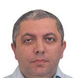 |
Kakha GorgadzeDoctor of Science / Principal Researcher |
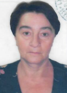 |
Iamze KalandadzeDoctor of Science / Researcher |
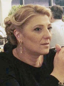 |
Shorena DekanosidzeDoctor of Science / Principal Researcher |
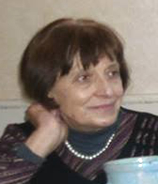 |
Nathalie FokinaDoctor of Science / Principal Researcher |
 |
Samson PagavaDoctor of Science / Researcher |
Amiran BibilashviliDoctor of Science / Principal Researcher |
|
Zura JibutiDoctor of Science / Principal Researcher |
|
NUgzar DolidzeDoctor of Science / Principal Researcher |
